MOUNTING CONSIDERATIONS / MOUNTING DIAGRAMS
When designing a new product that is to use reverberation, consideration should be given to where and how to mount the reverb. The reverb should not be thought of as an "add on" and simply mounted where there is space.
Two types of mounting are used on Accutronics' reverberation units. Larger units have mounting holes provided on the outer channel, while some companies use inner channels mounted with low-density foam tape. Some general mounting considerations, designed to minimize acoustical feedback and susceptibility to shock are given below:
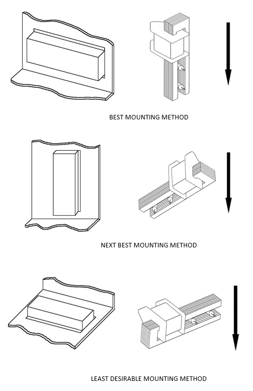
1. Accutronics units are designed to be mounted as shown in figures shown below. In this position the weight of the springs displaces the magnets along the air gap, not toward the lamination. The closer the magnet is to the lamination, the less of a shock can be given to the unit before the magnet will bottom on the laminations.
If the unit is going to be mounted in some other position, then when specifying your unit you should state the position. If the reverb is to be used in several different products, it will be to your advantage to specify a different model number for each different mounting position. We adjust the magnets at the factory so that they will be centered in the gap when installed.
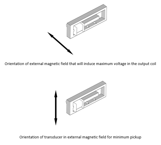
2. Even though the output transducer is shielded, the output end in particular should be kept away from transformer fields. The effectiveness of the shield varies with its orientation in an external magnetic field. The figures below show the orientations with respect to an external field for minimum and maximum pickup.
3. Hard mounting, such as bolting the outer channel directly to a case or cabinet wall should be avoided. Reverbs provided with mounting holes should be attached with grommets or rubber stand-offs to further increase mechanical isolation.
4. Placement on cabinet members that would tend to act as "sounding boards" should be avoided. A small-dimensioned rigidly supported surface is usually best.
5. Allow for slack in cables attached to the reverb to prevent forming mechanical feedback paths.
A frequently asked question about reverberation is what equalization, if any, should be used. Equalizing reverberation is a matter of application and mainly subjective taste. The DRIVER CIRCUITS on this site will give a good starting point since they provide an essentially flat response at the reverb output between 100 Hz and 5KHz. One type of equalization that should be considered in all applications is to add a low cut filter to the recovery amplifier. A filter with a 50 Hz to 100 Hz cutoff will lessen the effects of rumble when the unit is mechanically shocked.