In order to create a constant torsional force on the magnets, the flux in the air gap must remain constant. Since the flux in the gap is directly related in the number of amper-turns generated in the coil, the current thru the coil must remain constant to get a constant output voltage from the unit. The input transducer can be characterized as essentially inductive, with impedance rising with increasing frequency. In practice this means driving the transducer from a current source or from a voltage source equalized to give an output rising 6db/oct with increasing frequency. These types of circuits will maintain a constant value of amper-turns with frequency. With this in mind, consider the following points about the drive circuit
1. The first and foremost point to remember is to drive the unit as hard as practical. The core saturation level is approximately 2.5 A-T (amps measured RMS). The driver, at maximum expected input level, should drive the coil to near saturation. This is of utmost importance in applications where a speaker is mounted in the same enclosure as the reverb, such as a guitar amp or organ. This will allow the output or recovery amplifier gain to be reduced, lowering possibilities of feedback and minimizing microphonics. With today's solid-state circuitry and low supply voltages, low impedance coils (8ohm or 16ohm) should be used in high drive level applications. Popular operational amplifiers are limited in output capabilities and cannot drive the input transducer up to core saturation. For these high drive level applications, external transistors to boost operational amplifier current capabilities or monolithic power amps should be used.
For applications where the unit will not be subjected to mechanical vibrations, the eight circuit designs included will work quite well. Units should still be driven as hard as practical to provide the highest output voltage and therefore better noise performance from the recovery amplifier.
2. Although the reverb should be driven hard, driver overload or core saturation must be avoided. Distortions of any type will cause the reverberation to sound "muddy". Due to the varying nature of the reverb input as an amplifier load, the drive circuit can go quickly into overload, especially with high frequencies.
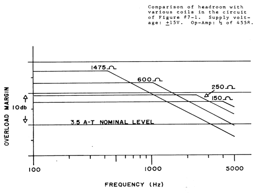
Consider the driver circuit titled "LOW COST INPUT DRIVE". Assume the use of an Accutronics' 150ohm coil specified at 6.5mA nominal drive and a desired response up to 5KHz. The voltage across the coil at 1KHz and 6.5mA would be 150ohm x 6.5mA = 1V (2.8Vp-p). Because the impedance of the coil increases directly with frequency, we can simply scale the voltage requirements for higher operating frequencies. Hence, (5KHz/1KHz) x 1 volt = 5V(14Vp-p). The Chart below illustrates the margin between the nominal 3.5 A-T level and driver overload for various coils using the circuit shown in "LOW COST INPUT DRIVE" the 150ohm - 250ohm coils provide the optimum performance with the single operational amplifier driver.
3. DC currents thru the coils should be avoided. Substantial DC currents will reduce the AC signal current swing possible before core saturation takes place.